 |
||||||
    |
||||||
| HOME l SERVICES l PRODUCTS l ABOUT US l CONTACT US | ||||||
|
-Case
study no1 |
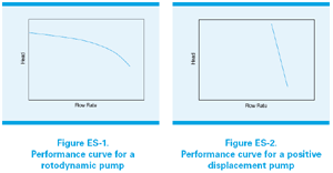
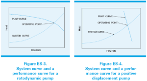
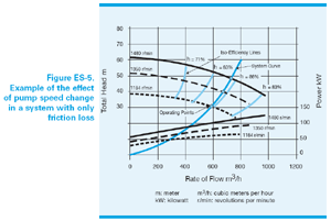
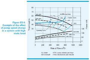
Variable Pumping Systems (part 2) Pump performance can be shown graphically as head against flow rate. The rotodynamic pump has a curve where the head falls progressively along with increasing flow. On the other hand, for a PD pump, the flow is pretty much constant whatever the head. It is customatory to draw the curve for PD pumps with the axes reversed, but for comparison, a common presentation is used here for two pump types: The effect of a pump being installed in the system can by illustrated graphically by superimposing pump and system curves. The operating point will be always where the two curves intersect. For a PD pump, when the system resistance raises (system curve is moving upwards) the pump will increase its discharge pressure and maintain fairly constant flow rate, dependant on viscosity and pump type. Unsafe pressure levels might occur without relief valves. For a rotodynamic pump, an increasing system resistance will reduce the flow, eventually to zero but the maximum head is limited. However this condition is only acceptable in the short run without causing problems. Adding comfort margins to the calculated system curve to ensure that a sufficiently large pump is selected will generally result in installing an oversized pump. In this case, the pump will operate with excessive flow rate (or will have to be throttled) leading to increased energy consumption and reduced pump life. Lots of pumping systems require a variation of flow or pressure. Either system curve or the pump curve needs be changed to get a different operating point. In case of a single pump (installed for a range of different duties), it would have been sized to meet the greatest output demand. It might be therefore oversized, and might be operating inefficiently for other duties. However, there is a way to achieve an energy cost savings by using control methods, such as variable speed. Such system will reduce the power to drive the pump during the periods of reduced demand. A rotodynamic pump is a dynamic unit with the head generated by a rotating impeller. Therefore, a relationship between impeller peripheral velocity and generated head occurs. Peripheral velocity is directly related to shaft rotational speed, for a fixed impeller diameter. Varying the rotational speed has a direct effect on the pump's performance. The equations relating rotodynamic pump performance parameters of flow to speed, and head and power absorbed to speed, are known as the Affinity Laws. Changing pump impeller diameter effectively changes the duty point in a given system. This can be used only for permanent adjustment to the pump curve at low cost, but is not discussed further as a control method. For systems where friction loss predominates, reducing pump speed moves the intersection point on the system curve along a line of constant efficiency (see image below). The operating point of the pump, relative to its best efficiency point, remains constant and the pump continues to operate in its ideal region. The Affinity Laws are obeyed, which means that there is a substantial reduction in power absorbed accompanying the reduction in flow and head, making variable speed the ideal control method. On the other hand, in systems with high static head, the system curve does not start from the origin but at some non-zero value (y-axis corresponding to the static head). Therefore, the system curve does not follow the curves of constant efficiency. Instead, it intersects them (see the image below). The reduction in flow is no longer proportional to speed; a small turn down in speed greatly decreases flow rate and pump efficiency. A common mistake is to use the Affinity Laws to calculate energy savings in systems with static head. Even though this can be done as an approximation, it can also lead to major inaccuracy. It is important to mention that flow control by speed regulation is always much more efficient than by a control valve. Apart from the energy savings, there could be other benefits to lower speed. The hydraulic forces on the impeller, (created by the pressure profile inside the pump casing) reduce approximately with the square of speed. These forces are carried by the pump bearings, and so reducing speed increases bearing life. It can be shown that for a rotodynamic pump, bearing life is proportional to the seventh power of speed. Additionally vibration and noise are reduced as well; therefore seal life is increased, provided that the duty point remains within the allowable operating range. |
|
||||
|
|
||||||
All Articles and Case Studies:
Case study no.1 (System upgrade to energy class 1) |
||||||
